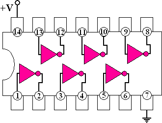
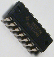
The 7404 IC package contains six independent positive logic NOT GATES (INVERTERS). Pins 14 and 7 provide power for all six logic gates.

|
DOWNLOAD
74LS04 DATASHEET
NOW (7404.pdf)

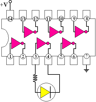
Shown above: The NOT gate on lines 3 and 4 will be put into an astable mode where no definite state can be resolved. Consequently, the LED will blink on and off at a rate dependent on the response time of the inverter gate (NOT gate) and prorogation delays. With adequate support electronics, the blink rate can be precisely controlled. Performing similar experiments can also allow the simple construction of AM radio transmitters, since the speed of most 7404 chips is well beyond the range of standard AM radios.

Outputs of one gate can be connected to inputs of another within the same chip or to another chip as long as they share the same ground. The figure to the left illustrates a basic circuit showing how to wire inputs and using LEDs to display outputs.
The 7404 is an inverting buffer, especially useful when the output of one circuit cannot sink much current. A computer's parallel port is a notorious example and can easily be damaged by excessive current draw. Each of the parallel ports outputs can be connected to one of the six inputs on the 7404 hex inverter chip. However, more than one 7404 will be needed to interface all of the parallel port pins.
NOT GATE Logic-Rules:
The output is the inverse of the input, in otherwords if the input is HIGH then the out put is LOW and if the input is LOW the output is HIGH.
|

