| HOME |
| CUSTOM DESIGN |
| PRODUCTS |
| CONTACT |
| CIRCUITS |
| FAQs |
| RESOURCES |
| LINKS |
| ABOUT |
|
The
74HC574 IC package is
an 8-stage (octal) D Flip Flop circuit.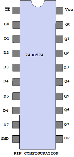 |
DOWNLOAD 74HC595 DATASHEET NOW (74HC574.pdf) 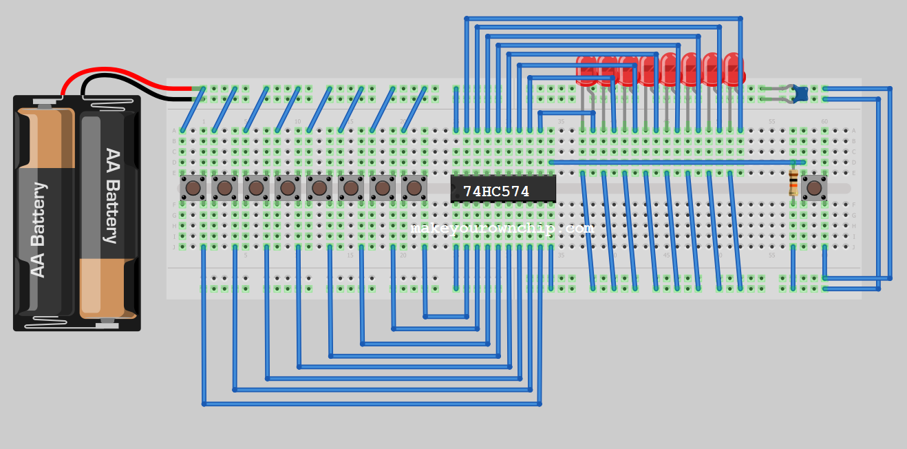 In the circuit above, eight push button switches are connected to the 8 inputs (D0-D7) of the 74HC574 chip. When a button is held down a logical 1 is presented to the input pin, otherwise a zero will be interpreted (pull down resistor may be required). The button on the far right is tied to the CP pin. Clicking the CP button will transfer the state encoded by the eight buttons into the light pattern on the eight LEDs (connected to the 74HC574's 8 outputs (Q0-Q7). Once the state is latched, removing the hands from the eight buttons will have no effect. The chip will remember the state, until a new state is clocked in!  |
 |
The
74HC595 is an octal (8) D type Flip Flop. Each D Flip Flop circuit has
a non-inverting 3-state output (pins Q0-Q7). When the !OE pin
is high, the outputs switch to their hi-impedence off state. Multiple
74HC574 chips can have their outputs connected in parallel as long as
only one (the active chip) in the arrangement is active at any time. In
this way, the 74HC574 can function in a parallel bus fashion. When the
!OE pin is low, the contents of the D latches, are made available to
the output pins. Data present on the data input pins (D0 - D7) will internally register upon the positive edge pulse on the CP (clock input) pin. The states of the registers will output to the output pins (Q0-Q7) if the !OE pin is low. Features: 3-state outputs 123MHz Max Clock Frequency (HC) or 76MHz for HCT) * Serial I/O or Serial In - Parallel Out (For use as a serial to parallel data converter) Asynchronous reset allows all (8) eight stages to be cleared simultaneously. *Check with manuafcturer specific datasheet for exact statistics. |